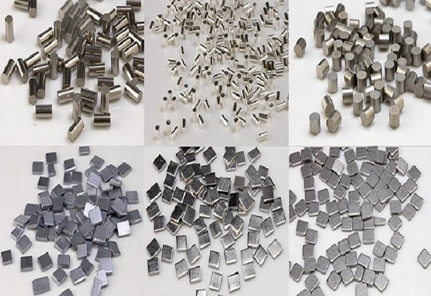
Vacuum evaporation coating is a common method used to deposit thin films onto a substrate. This technique is widely used in a variety of industries, such as electronics, optics, and aerospace, due to its ability to create precise and uniform coatings with a high level of purity. There are several mechanisms used to achieve vacuum evaporation coating, each with its own advantages and limitations.
RESISTANCE EVAPORATION
One common method is resistance evaporation, which uses a resistance evaporation source made of tungsten, molybdenum, or tantalum to evaporate low melting point materials such as gold, silver, zinc sulfide, magnesium fluoride, chromium oxide, and others. However, this method may not meet the needs of vapor deposition of certain metals and non-metals.
ELECTRON BEAM EVAPORATION
Electron beam evaporation is another technique used for vacuum evaporation coating. It involves heating the evaporating material with an electron beam, which can provide a much larger energy density than the resistance heat source. This allows for the heating of refractory metals and non-metallic materials such as tungsten, molybdenum, niobium, SiO2, AI2O3, and others. Additionally, the material to be vapor-deposited is placed in a water-cooled crucible, which helps to avoid evaporation of the container material and reaction between the container material and the membrane material, thus improving the purity of the membrane.

HIGH-FREQUENCY INDUCTION HEATING EVAPORATION
High-frequency induction heating evaporation is another method used for vacuum evaporation coating. The metal is heated to the evaporation temperature using the principle of induction heating. The crucible containing the evaporation material is placed in the center of the spiral coil, and a high-frequency current is passed through the coil to heat the metal evaporation material until evaporation. This method has a large evaporation rate, uniform and stable evaporation source temperature, easy temperature control, and requires less purity of the evaporation materials.
ARC HEATING EVAPORATION
Arc heating evaporation uses the arc discharge heating method, which is similar to the electron beam heating method. This method is particularly suitable for evaporation of refractory metals and graphite that have a high melting point and a certain conductivity. It also has the advantage of being relatively inexpensive compared to the electron beam heating apparatus.
CONCLUSION
In conclusion, vacuum evaporation coating is a versatile and widely used technique for depositing thin films onto a substrate. There are several methods used to achieve this, each with its own advantages and limitations. By understanding the different mechanisms of vacuum evaporation coating, researchers and industry professionals can choose the appropriate method to achieve the desired coating properties for their specific applications.
If you want to learn more about sputtering targets, such as metals, alloys, oxides, and ceramic materials, you can visit the website of Stanford Advanced Materials (SAM) Corporation at https://www.sputtertargets.net/. SAM is a global supplier of various sputtering targets and regularly updates their knowledge and interesting stories related to sputtering targets on their website.


