What are the advantages of carbon fiber composite materials used in aeroplanes?

Carbon fiber is a kind of special fiber mainly composed of carbon element and generally contains more than 90% carbon. Carbon fiber has the characteristics of high-temperature resistance, friction resistance, electrical conductivity, thermal conductivity, and corrosion resistance to general carbon materials. However, unlike ordinary carbon materials, its shape has significant anisotropy, and it shows strong strength along the fiber axis.

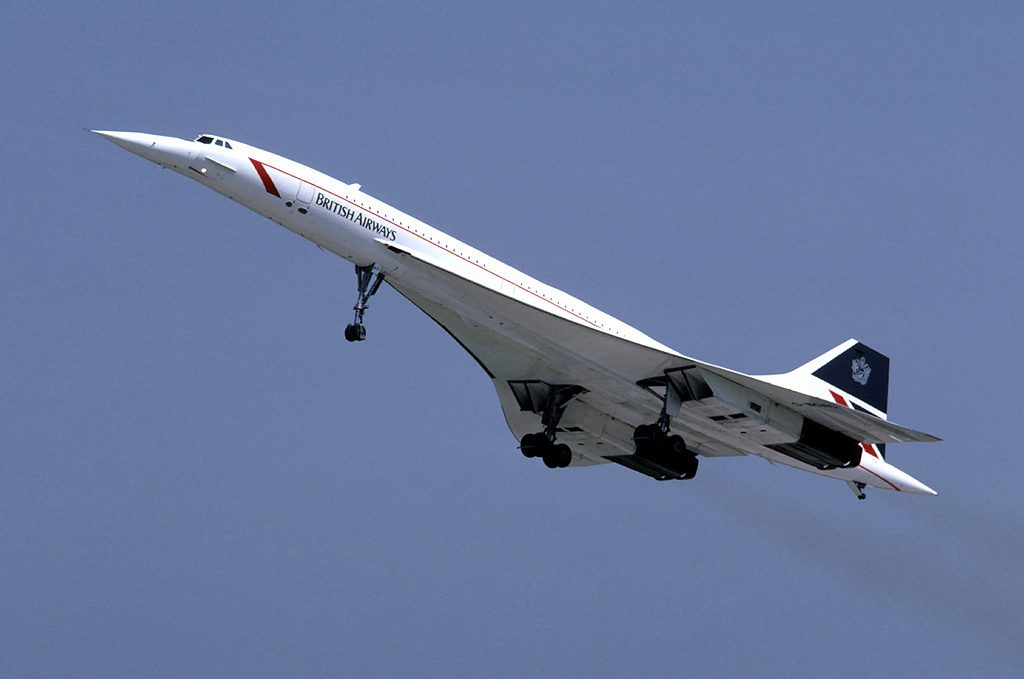
With its own unique advantages, carbon fiber reinforced composites have also been widely used in the aircraft manufacturing industry. Especially for smaller airplanes, carbon fiber composites are the best choice.

As a kind of carbon fiber, carbon fiber composite material has a wide range of applications in many fields due to its characteristics of high strength, lightweight, stable chemical properties, high-temperature resistance, and strong durability. Applying it to the fuselage and wings of an airplane can reduce the weight of the airplane by about 40%, and its crawling ability can be increased by 1.8 times compared with the airplane of ordinary materials.

Compared with military and civil aircraft, model aircraft are smaller in size, shorter in-flight operation time, and the working environment is relatively better. Applying carbon fiber composite materials to model aircraft can increase their service life, so they can be applied to the harsh environments.

aircraft concord

The application of carbon fiber composite materials to airplane aircraft can not only reduce the mass of the airplane but also increase the strength tolerance range of the airplane aircraft to a certain extent. The fuselage and propeller made of carbon fiber composite materials reduce the weight of the airplane while increasing its strength, thereby reducing its volume.

With the continuous development of the aerospace industry, the demand for carbon fiber composites is increasing. At the same time, people have put forward higher requirements for the quality of carbon fiber composite materials, which in a certain sense promotes the development of carbon fiber composite materials in the direction of multifunctionality, low cost and high performance.

Compared with glass fiber, the application cost of carbon fiber is also relatively high, and it is more difficult to promote and use it in a wide range. From the current situation, the price of carbon fiber materials has not only declined, but also shown an upward trend. To solve this problem, new processes must be studied to reduce the cost of carbon fiber composites.

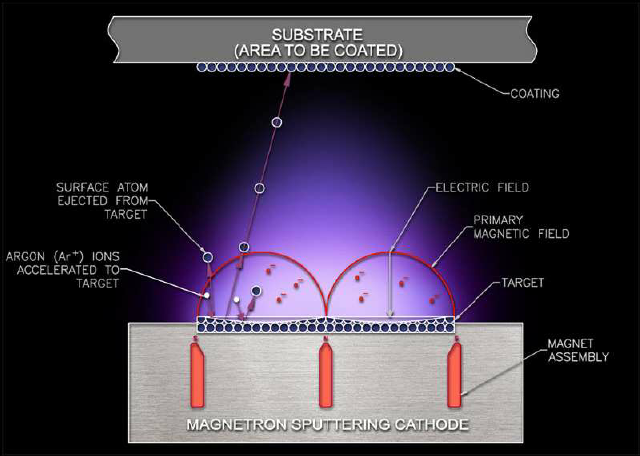
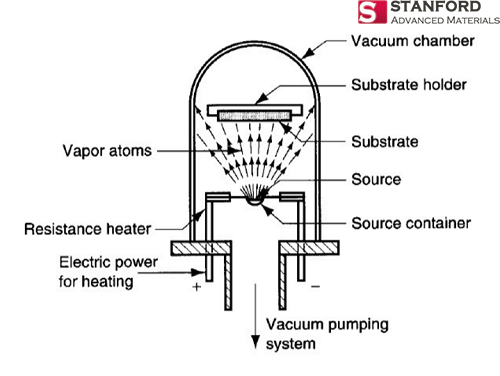
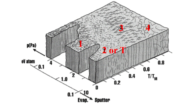
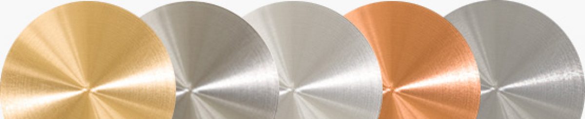
Carbon fiber materials can also be made into the carbon sputtering target for aviation coatings. Stanford Advanced Materials provides high-quality sputtering targets and evaporation materials. Please visit https://www.sputtertargets.net for more information.

Preparation of Molybdenum Sputtering Targets by Powder Metallurgy

Molybdenum film has many advantages such as good electrical conductivity and thermal stability, chemical resistance, and low thermal expansion coefficient. It has been widely used in solar power generation, computer circuits, flat panel displays, storage media, and other aspects.

The magnetron sputtering technology has many advantages such as densely rented thin films, low surface roughness, good film-base bonding force, high deposition rate, low substrate temperature, and convenient deposition of thin films with high melting points. It is currently the main method for preparing molybdenum films using molybdenum sputtering targets.

Previous studies have shown that the choice of different magnetron sputtering equipment and process parameters (target current, target power, gas pressure, sputtering time, etc.) should also have a close relationship with the differences in the structure and performance of the sputtered thin films.

molybdenum target powder metallurgy

The electronic display industry’s technical requirements for sputtering targets mainly include indicators such as chemical purity, density, grain size and size distribution, grain orientation and orientation distribution. Recent studies have shown that the smaller the grain size of the target, the higher the sputtering rate; the more uniform the grain size distribution of the target, the easier it is to obtain a sputtered film with uniform thickness.

Since molybdenum is a high melting point (2620 ° C) metal. Powder metallurgy is the main method for preparing molybdenum targets. The process mainly includes the steps of milling, pressing, and sintering.

The powder metallurgy method is a technical method in which metal powders, alloy powders or mixed powders of metals and non-metals are directly made into various products through pressing, sintering and other processes. The main feature of this method is that it can produce special material products that are difficult to achieve or cannot be manufactured by conventional metallurgical methods or material processing methods, such as parts of machines made of refractory tungsten and molybdenum metals.

The main features of powder metallurgy are: the raw materials can be directly manufactured into qualified products according to the shape and size requirements of parts and components without mechanical cutting or slight cutting; suitable for mass production and high efficiency; Less waste during production and high utilization of raw materials. This method has been widely used in the automotive industry, energy industry, chemical industry, national defense industry, and aviation and aerospace industries.

For more information, please visit https://www.sputtertargets.net/.

Advantages of Sputtering Deposition and Vacuum Evaporation

For all devices, there is a need to go from semiconductor to metal. Thus we need a means to deposit metals, also called film coating. There are currently several methods for depositing metal thin film layers, and many of these techniques for metal deposition can also be used to deposit other materials.

1.) Physical Vapor Deposition (PVD)

2.) Electrochemical techniques

3.) Chemical Vapor Deposition (CVD)

This passage will talk about the advantages of two PVD methods: Sputtering and evaporation.

Sputtering Deposition

magnetron-sputtering-system
Magnetron Sputtering System

The plasma under high pressure is used to “sputter” metal atoms out of the “target”. These high-energy atoms are deposited on a wafer near the sputtering target material. Higher pressures result in better step coverage due to more random angular delivery. The excess energy of the ions also helps increase surface mobility (the movement of atoms on the surface).

Advantages: Better step coverage, less radiation damage than E-beam evaporation, easier to deposit alloys.

Disadvantages: Some plasma damage including implanted argon. Good for ohmics, not Schottky diodes.

Vacuum Evaporation

Evaporation (PVD)
Evaporation (PVD)

Evaporation is based on the concept that there exists a finite “vapor pressure” above any material. The material either sublimes (direct solid to vapor transition) or evaporates (liquid to vapor transition).

Advantages: Highest purity (Good for Schottky contacts) due to low pressures.

Disadvantages: Poor step coverage, forming alloys can be difficult, lower throughput due to low vacuum.

PVD Film Morphology

The three zone model of film deposition as proposed by Movchan and Demchishin

1.) Porous and/or Amorphous —> Results from poor surface mobility =low temperature, low ion energy (low RF power/DC bias or higher pressures=less acceleration between collisions).

2.) “T-zone”: Small grain polycrystalline, dense, smooth and high reflectance (the sweet spot for most metal processes) Results from higher surface mobility =higher temperature or ion energy

3.) Further increases in surface mobility result in columnar grains that have rough surfaces. These rough surfaces lead to poor coverage in later steps.

4.) Still further increases in surface mobility result in large (non-columnar) grains. These grains can be good for diffusion barriers (less grain boundary diffusion due to fewer grains) but pose problems for lithography due to light scatter off of large grains, and tend to be more rigid leading to more failures in electrical lines.

For more information, please visit https://www.sputtertargets.net/.