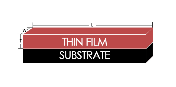
The planar magnetron is an exemplary “diode” mode sputtering cathode with the key expansion of a permanent magnet cluster behind the cathode. This magnet exhibit is organized so that the attractive field on the substance of the target is ordinary to the electric field in a shut way and structures a limit “burrow” which traps electrons close to the surface of the target. This enhances the effectiveness of gas ionization and compels the release plasma, permitting higher presence at the lower gas weight and attaining a higher sputter affidavit rate for Physical Vapor Deposition (PVD) coatings.
Although some distinctive magnetron cathode/target shapes have been utilized in magnetron sputtering processes, the most widely recognized target types are circular and rectangular. Circular magnetrons are all the more regularly found in littler scale “confocal” cluster frameworks or single wafer stations in group instruments. Rectangular Magnetrons are frequently found in bigger scale “in line” frameworks where substrates examine straightly past the focus on some type of carpet lift or transporter.
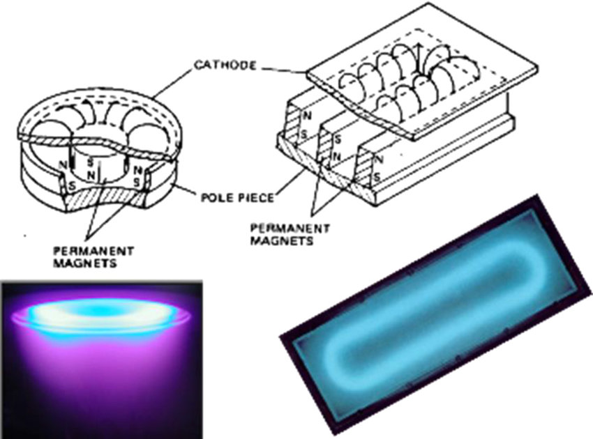
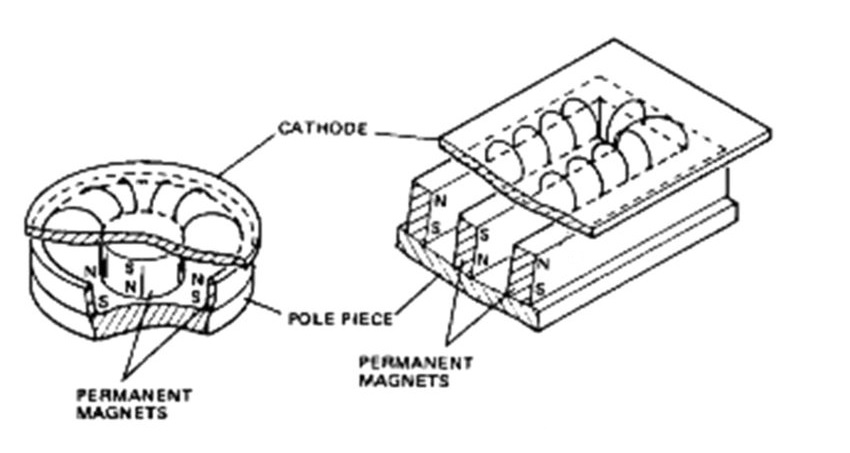
Most cathodes – including practically all circular and rectangular ones – have a straightforward concentric magnet design with the middle being one shaft and the edge the inverse. For the circular magnetron, this would be a generally little adjusted magnet in the middle, and an annular ring magnet of the inverse extremity around the outside with a hole in the middle. For the rectangular magnetron, the core one is typically a bar down the long hub (however short of the full length) with a rectangular “wall” of the inverse extremity and the distance around it with a hole in the middle. The crevice is the place the plasma will be, a roundabout ring in the circular magnetron or a lengthened “race track” in the rectangular.
The magnetron works with either an attractive arrangement – the middle could be north and the border might be south, or the other way around. Notwithstanding, in most sputter frameworks, there are various cathodes in reasonably close vicinity to one another, and you don’t need stray north/ south fields structured in the middle of the targets.
Those N/S fields ought to just be on the targets’ confronts, structuring the coveted attractive shafts there. Hence, it is completely attractive to verify all the cathodes in one framework are adjusted the same way, either all north on their borders or all south on their edges. What’s more, for offices with numerous sputter frameworks, it is similarly alluring to make all of them the same so cathodes can securely be traded between the frameworks without agonizing over magnet arrangement.
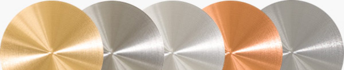
There are extra contemplations and choices in regard to the magnets. Most target materials are nonmagnetic and in this manner don’t meddle with the obliged attractive field quality. However, in the event that you are sputtering attractive materials, for example, iron or nickel, you will require either higher quality magnets, more slender targets, or both with a specific end goal to abstain from having the surface attractive field adequately shorted out by the attractive target material.
Past that, the magnet’s subtle elements, for example, attractive quality and crevice measurements, might be intended to enhance target material usage or to enhance consistency along the vital pivot of a rectangular target. It is even conceivable to utilize electromagnets rather than perpetual magnets, which can manage the cost of some level of programmable control of the attractive field, yet does, obviously, build many-sided quality and expense.
For more information, please visit https://www.sputtertargets.net/.